| Home |
| Stirling Engines |
| State of the Art |
| Theory |
Theory 1 - Generic schematic
The simple Stirling engine is schematically represented with four components:
1) a heat source
2) a working module
3) a heat sink
4) an energy buffer
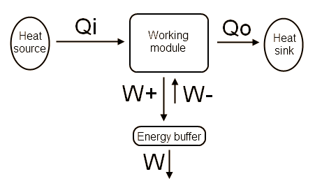
Heat source
This component is the hot part of the engine, it provides the raw thermal energy Qi to the working module
Working module
This component consists of several volumes filled with a working fluid, piston(s) and/or displacer as well as a shaft mechanism and potentially other mechanical components. This module converts some of the input thermal energy Qi into mechanical energy W and releases some thermal energy Qo to the heat sink.
Heat sink
This is the cold part of the engine, the role of the heat sink is to evacuate the thermal energy Qo that has not been converted into mechanical work.
Energy buffer
During some part(s) of the thermodynamic cycle, the working module needs to give back some energy to the working fluid. The energy buffer is the temporary energy storage system where this energy is kept before to be partially re-injected in the working fluid to complete the cycle. Usually the energy buffer is made of flywheel(s) and connecting parts or spring.
More complex engines are composed of several working modules, the energy buffer can be avoided by coupling these modules with the adequate phase shift.
|
Theory index Theory 1 - Generic
schematic |